Aug 14, 2012
Join the "CWTD Yahoo Group" for
email discussion in between our weekly sessions by clicking
here.
Analyze This!
Dissecting and analyzing the 8640-Jr Signal Source!
A continuation in our Component Selection
series
Many times when we see plans for a good project we think
"Hey, I'd like to make this project but ..."
we don't have the exact parts called for. But if we dig around in the junk
box for parts we do have
we can often use them just fine by altering the project specs or schematic
accordingly.
This week's program focuses on ... Analyzing a circuit for
component choice and usage.
Overview
Okay, time to roll up our collective sleeves and start
applying the guidance shared over the last 2-3 episodes of CWTD.
We
have a fascinating and extremely useful circuit that can be analyzed, diagnosed, enhanced,
optimized, measured, and simplified ... all using the techniques we've been
discussing during our recent "component selection" programs. We think
you'll love this exercise! And
better yet, you'll get the hang of looking at circuits the way designers do when
it comes to component selection and making custom enhancements.
73, George N2APB & Joe N2CX
Audio Recording
... (Listen
to the MP3 podcast)
Discussion
Notes:
<20:00:51> "Rick K3IND": I like the new CWTD page header!
<20:00:52> "Ray K2ULR": <http://dl.dropbox.com/u/43021514/CWTD/Aug%2014.html>
<20:01:42> "Armand WA1UQO": The new banner for the Teamspeak homepage looks
great!
<20:09:35> "George - N2APB": Hope everyone has our whiteboard up on your screen,
as we'll be talking directly to the schematics on the page. ...
http://dl.dropbox.com/u/43021514/CWTD/Aug%2014.html
<20:14:15> "Joe N2CX": BTW the neat schematic we present here was drafted by
Paul Harden NA5N
<20:31:20> "Joe N2CX": Oscillator runs ar 13.6 to 30 MHZ
<20:33:36> "Pete - WB2QLL": What does D1 do?
<20:33:53> "Lee KM4YY": What does D1 do?
<20:34:13> "Paul KD7KDO": How much current does the VFO draw?
<20:35:34> "Joe N2CX": And software costs $$$$$
<20:37:07> "Paul KD7KDO": So you get a pretty good sinewave?
<20:46:04> "Paul KD7KDO": How many turns is in this transformer?
<20:48:01> "George - N2APB": 12T = 12 Turns
<20:50:01> "Rick K3IND": what about R17?
<20:50:43> "George - N2APB": provides bias for Q4
<20:51:58> "Mike WA8BXN": what kind of feedback is there in Q4 with R17
connected to the collector rather than +5V?
<20:58:34> "George - N2APB": Haiku = Hi-Q
<20:58:44> "Paul KD7KDO": Shouldn't the input and output impedance of the filter
be set at the same 50 Ohm impedance?
<20:59:26> "Joe N2CX": A tad of signal feedback but the main reason is that the
bias gives you good gain to square up the input sine wave
<20:59:57> "Al K8AXW": Can the NP0 caps be replaced with silvered mica?
<21:00:14> "Joe N2CX": Normally the filter is 50 ohms at both ends. I presume
that W7ZOI found that a good termination at one end is sufficient.
<21:00:44> "Joe N2CX": Silver mica is fine if you have them or lots of $$$
<21:01:40> "Pete - WB2QLL": That probably should be RXTX 6.3....
<21:08:36> "Mike WA8BXN": how was the number of turns picked for T2?
<21:09:47> "Joe N2CX": Enough turns to give high reactance of the transformer
winding to preserve good low frequency performance.
<21:10:36> "Joe N2CX": Rule of thumb is that a transformer inductance needs to
be at least 4-19 times the operating impedance level.
<21:10:49> "Joe N2CX": That's 4-10 times...
<21:12:18> "Paul KD7KDO": Can you comment on shielding needed for something like
this ... orfor the attenuator if you put one at the output...
<21:14:05> "Joe N2CX": TIf you intedn to use an external attenuator the whole
thing needs to be mounted in a good shielded box to eliminate leakage.
<21:15:22> "Peter SV0XAW": found this on youtube
http://www.youtube.com/watch?v=abFqtb6u418
<21:16:46> "Mike WA8BXN": will any kits be ready for the in person meeting?
<21:16:49> "Joe N2CX": Thanks Peter I'll cheeck it out after the session.
<21:16:51> "Armand WA1UQO": Any update on the Paul Harden data book?
<21:17:42> "Joe N2CX": No news on the Harden book.
<21:17:59> "Joe N2CX": Don't know if there will be kits for the in-person
meeting.
<21:20:35> "George - N2APB": Search for the "Wayback Machine" to look for a way
to find information from websites that are no longer in existence.
<21:20:38> "Al K8AXW": Good job gentlemen!!
<21:21:49> "Al K8AXW": what is the url for the yahoo group?
<21:22:58> "Frank N3PUU": Great job guys! 73 and see you on Saturday..
<21:23:29> "Al K8AXW": TY George AR K
<21:23:43> "Joe N2CX":
CWTD-subscribe@yahoogroups.com
SESSION NOTES
Do schematics
sometimes look
like this to you? ...
Well, it doesn't
always have to be that way. If you can break the schematic down into
functional blocks and then consider the role of some key components, you'll get
an idea for the way the project is intended to operate. And THEN, you'll
have a better handle on how you could go about modifying it to better suit your
intended use. Or perhaps instead of immediately needing to buy new
components, you might have a better feel for finding something in your junk box
that will do the job equally as well!
So let's get into
it straight away and first consider a very useful and powerful circuit from
W7ZOI called the "8540-Jr Oscillator".
·
Designed by Wes Hayward W7ZOI
·
Inspired by legendary HP8640 signal generator
·
Circuit Functions
◦
Overall – Tunable reasonable quality test oscillator
▪
Tunes 3.4 – 30 MHz in three bands
·
Main tuning and bandspread
▪
Good buffering and filtering for stability and signal purity
◦
Hartley oscillator with air-variable tuning capacitors
▪
Range 13.6-30 MHz sine wave output
▪
Divide by 2 and low pass filter for 6.8-15 MHz
▪
Divide by 4 and low pass filter for 3.4-7.5 MHz
◦
Voltage regulator aids frequency stability
◦
Buffer amps help maintain stability and low harmonics
·
Voltage regulator
◦
Integrated circuit 7806 gives good regulation
◦
SEPARATE VOLTAGE REGULATOR FOR OSCILLATOR TO KEEP OUT DIGITAL
NOISE FROM DIGITAL CIRCUITS
◦
6v REGULATOR VS 5V TO GET MOST PERFORMANCE FROM Q1 AND Q2
◦
Ceramic bypass caps in and out for filtering and eliminate
instability
·
Variable oscillator
◦
Hartley circuit for wide tuning range
◦
Air variable tuning caps for good stability
▪
365 PF TC1 (TUNING CAPACITOR 1) IS MAIN TUNING
▪
35 PF TC2 IS FINE TUNING
◦
JFET for minimal circuit loading
▪
2N4416 IS JUNCTION FET
▪
HAS HIGH GAIN AND LOW STRAY C UP TO VHF
▪
OTHER FETS – 2N3819, 2N5485, MPF102 WILL WORK BUT HAVE WIDER
SPREAD OF CHARACTERISTICS SO MAY NEED SELECTION
◦
Diode on FET gate provides amplitude self-adjustment
▪
ALONG WITH C8 AND R4 RECTIFY SMALL AMOUNT OF OSCILLATOR SIGNAL AND
APPLY NEGATIVE FEEDBACK AS OSCILLATOR OUTPUT TRIES TO CHANGE
◦
Iron core toroid for tuning inductor for good stability and low
loss
◦
NPO caps in tuned circuit for stability and low loss
▪
C5, C6 C7 AND C8
◦
100 ohm resistor in drain circuit to prevent VHF instability
▪
SINCE JFET HAS GAIN UP TO VHF EVEN WIRING CAN ACT AS TUNED
CIRCUIT. 10 OHM RESISTOR R5 “DE-Q'S” THE STRAY INDUCTANCE
·
Two-stage follower/buffer amp isolates oscillator
◦
JFET Q2 follower for low oscillator circuit loading
▪
ANOTHER JFET WITH HIGH INPUT IMPEDANCE
▪
DRAIN RESISTOR R6 DE-Q'S STRAY INDUCTANCE TO PREVENT VHF
OSCILLATION
◦
Bipolar transistor Q3 provides high RF gain 2N3904 USED BUT
2N4401, 2N2222 ALSO GOOD CHOICES
▪
CONNECTED IN COMMON GATE AMPLIFIER CONFIGURATION WHICH HAS VERY
LOW OUTPUT TO INPUT STRAY C FOR GOOD ISOLATION
▪
DRAIN RESISTOR R12 PREVENTS VHF OSCILLATION
◦
XXXXXXX OUT drain and resistor resistors minimize instability
◦
independent RC filters in DC SUPPLY TO each stage for clean
signals
◦
Output buffer uses wideband xfmr on ferrite toroid core
▪
bifilar winding for ease of construction
▪
2:1 IMPEDANCE RATION ASSURES THAT Q3 COLLECTOR SEES HIGH IMPEDANCE
FOR BEST GAIN
·
Highest 2:1 freq range feeds sine wave directly to output buffer.
(13.6 TO 31 MHZ)
·
Other ranges gotten from digital divider chain
◦
Additional RC filtering and 7805 regulator in digital DC power
assure clean signals
◦
Second tuning range from squaring amp and divide by 2 flip flop
◦
SQUARING AMPLIFIER IS BIPOLAR 2N3904 BIASED AS LINEAR AMP BUT
OVERDRIVEN BY SINE WAVE INPUT TO PRODUCE SQUARE WAVE OUTPUT
◦
DIGITAL DIVIDER 74HC74 TYPE DEVICE WORKS WELL UP TO 30 MHZ AND
DRAWS LESS POWER THAN OTHER 74XX74 TTL TYPES
◦
FIRST DIVIDE BY 2 CIRCUIT PROVIDES SQUARE WAVE OUTPUT OF APPROX
6.8 TO 15 MHZ
◦
SQUARE WAVE OUTPUT IS CLEANED UP TO SINE WAVE BY LOW PASS FILTER
▪
SQUARE WAVE CONSISTS MAINLY OF FUNDAMENTAL FREQUENCY AND ODD
HARMONICS (3, 5, 5 ETC.)
◦
Third tuning range additional divide by 2 flip flop (total of
divide by 4) FOR 3.4 TO 7 MHZ TUNING RANGE
▪
Square wave output OF DIVIDERS cleaned up by low ripple steep
cutoff LPF
·
.07 Db CHEBYCHEV DESIGN
◦
Low ripple to keep output constant across frequency
◦
steep rolloff removes 3rd and higher harmonics of
square wave
◦
Low pass filters use iron core toroid inductors and NPO capacitors
for low loss
▪
MAY NEED TO CHECK INDUCTANCE AND CAPACITANCE OF EACH COMPONENT AND
TWEAK INDUCTORS TO GET BEST AMPLITUDE STABILITY ACROSS EACH BAND AND MINIMAL
HARMONIC CONTENT
◦
Low pass use resistive input attenuation to preserve passband
response
·
output buffer uses resistive feedback for flat frequency response
◦
On both emitter and base BIAS RESISTORS ARE BYPASSED BY OTHER
RESISTORS WITH DC BLOCKING CAPACITORS TO LESSEN NEGATIVE FEEDBACK THUS
INCREASING GAIN
Another
RF Signal Source: the "8640-Jr"
Wes Hayward, w7zoi,
26feb12, update 28/29Mar12, 9apr12.
(Click to download a PDF the article.)
Radio Frequency signal
sources are like power supplies: we can always use one more of them. This signal
source is based upon the Hewlett-Packard HP-8640B, which is one of the most
popular generators available. The generator is no longer available new, having
been replaced by more up to date synthesized instruments. But the 8640 is still
available and popular on the surplus market. The HP-8640 uses a single variable
oscillator operating at VHF. That source is then frequency divided to generate
the various bands. The phase noise and stability get better as the division
ratio increases. This divider chain basis is used in our design, although with
significant simplification.
This signal source
consists of a Hartley oscillator operating from 13.6 to 32 MHz. It is necessary
to have a tuning range of at least one octave to really take full advantage of
this divider topology. This range is available directly, or is divided by 2 or
4, providing output all the way down to 3.4 MHz. Each of the two divided ranges
is filtered with a 5th order low pass filter. Only one such filter was used for
each band. Each was designed for a cutoff frequency just above the top of the
range. The passband ripple was varied to achieve convenient, off the shelf
capacitor values in the filters. The harmonic suppression is reasonable, but is
much worse than the instrument's namesake. The original HP-8640B has a stellar
harmonic suppression of over 60 dB, which resulted from the use of 3 filters for
each octave. The excellent suppression is atypically good for a signal
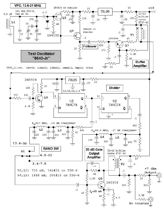
generator. Our 8640-Jr signal source is shown in the schematic of Fig 1.
Note that we don't call
this a signal generator. A signal generator is a well shielded instrument
that can be used to measure the sensitivity (MDS) of a serious detectors of only
modest sensitivity such as oscilloscopes. Not only is shielding good, but a
signal generator is immune to interactions from other generators that might be
attached. A modern signal generator has a well defined, low output impedance,
usually 50 Ohms. Frequency stability is, of course, good. Our little offering
does not fit all of these criterion. It is, however, reasonably stable.
Moreover, the oscillator is well isolated from external influences, allowing it
to be used with another similar unit for the evaluation of IMD of mixers or
amplifier in the lab.
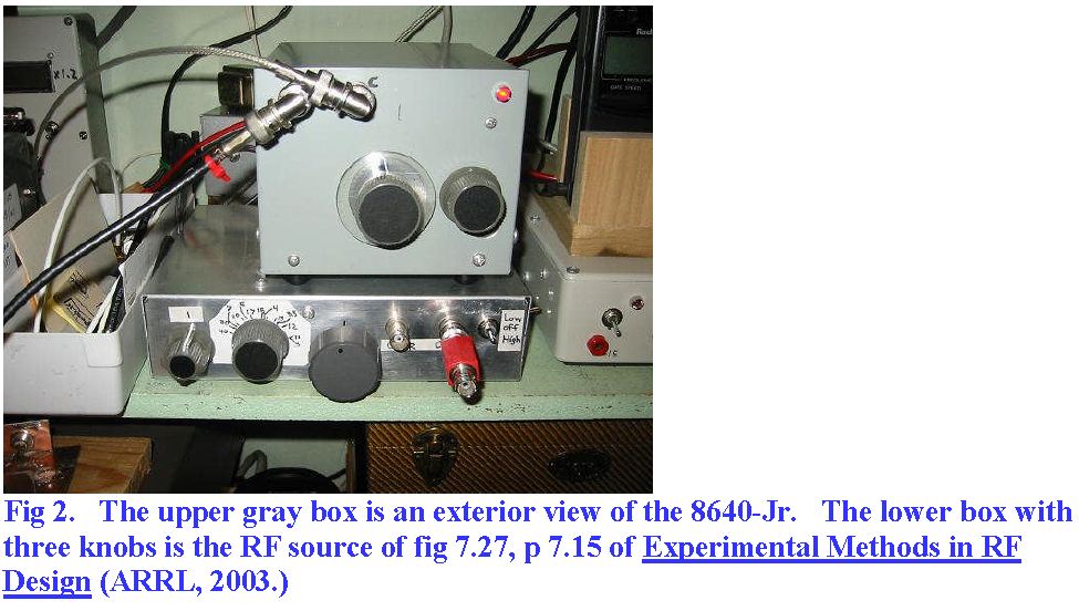
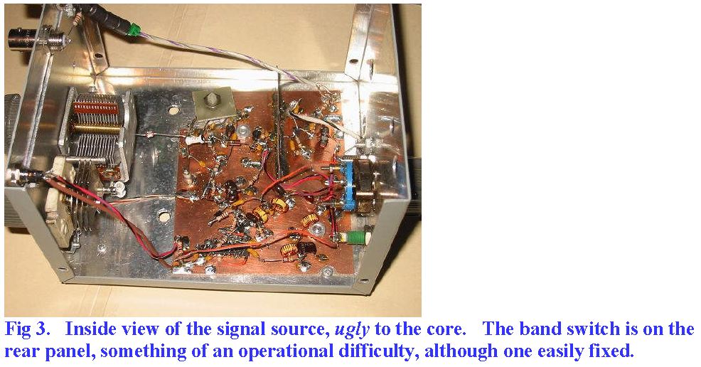
Photos of the rf source are shown
below.
Examination of Fig 1 and
of Fig 7.27 of EMRFD will show considerable similarity. In spite of this, this
experiment provided a few interesting details which we will outline here.
The signal is extracted
from the VFO with a source follower while it was pulled from the EMRFD signal
source with a single turn link through the tank coil. The link is the preferred
method, for the harmonic output is lower by over 20 dB. While the output
amplifier contributes some of the harmonic distortion, the dominant contributor
is the follower.
The secret of this
design, although it is certainly not a secret, is the common base buffer. This
was originally inserted in the EMRFD RF source when we tried to use the
instrument to examine a crystal filter. The VFO would try to lock to the
crystals when the output was reflected from the crystal filter and back through
the output stage to the VFO. The extra buffer with it's excellent reverse
isolation completely eliminated this difficulty. The rf source had not been
usable for IMD measurements until the common base buffer was added.
The VFO in the '-Jr
originally used a 2.2 pF gate capacitor. The particular JFET we were using and
perhaps the gate diode combine to compromise the starting gain for the
oscillator. The circuit would change output level when at the lower end of the
tuning range. The changes were often in the form of sharp steps in output level
as frequency was changed. Changing the gate capacitor from 2.2 to 4.3 pF
completely eliminated this problem.
Note the method of
extracting signals from the divider chips. In each case, a large capacitor
provides DC blocking so the following resistors do not alter the DC conditions
on the CMOS chip. A voltage divider then drops the level to that needed to drive
the output amplifier. The 680 Ohm resistor provides a high Z load that the
divider can drive while the 51 Ohm resistor provides the proper resistance to
terminate the low pass filter. When first built, the 8640-Jr used a classic
surplus variable capacitor from a WW-II BC434 Command Receiver. These feature a
built in gear reduction drive (about 60:1) and a dial mechanism, all in a
package that is surprisingly easy to mount and use. But there seemed to be
problems with excess noise as the circuit was tuned. The capacitor was changed
to another from the junk box, but the same problems were there. Eventually, they
were traced to the inadequate starting gain mentioned above. But this had not
been confirmed until the capacitor had been swapped out for the 365 pF AM
broadcast band capacitor. The combination of two capacitors works well, although
the band spread is extreme at the low end of the tuning range while almost
inadequate at the high end.
It was recently
(28Mar12) brought to my attention that an enterprising purveyor of radio kits
has decided to assemble a sack of parts for this design and offer it to the
amateur radio community. He says that he will use polyvaricon variable
capacitors instead of the air variables that I used. This could lead to
problems. See my Q measurement results on these parts at
http://w7zoi.net/2faces/twofaces.html.
This design uses an
output amplifier biased to about 20 mA emitter current. The similar stage in the
EMRFD circuit, Fig. ,7.27 had a current of 35 mA. This means that the output
stage of the EMRFD circuit could be driven harder. This means that either the
output could be higher, or that a larger output pad could be employed. Both
would be an advantage.
There is no adjustment
of output level. Some sort of variable attenuator would be handy such as the pot
adjusted circuit of Fig. 7.22. Alternatively, a PIN diode attenuator would do
the job.
Spectral analysis of the
output is interesting. The harmonic attenuation is poor as mentioned above and
depends upon the band selected as well as the position within the band. The high
band, even when neither digitally derived output is in use, still has a spur at
half the output frequency, but it is at about -55 dBc. This is some of the
digitally derived lower frequency leaking through. Experimentation and design
refinement would probably improve this problem.
The schematic diagram is
labeled with an output power of +7 dBm. This is approximate. The following data
was measured, showing a slight variation from the nominal value:
High band
+9.2 dBm at 13.6 MHz
+7.6 dBm at 32.6 MHz
Mid band
+4.8 dBm at 16.3 MHz
+8.0 dBm at 6.8 MHz
Low band
+6.8 dBm at 8.17 MHz
+8.2 dBm at 3.4 MHz
The low pass filters are
purposefully designed for a cutoff that is close to the top of the respective
bands. Hence, it is important to actually measure the inductance can
capacitance value, or
otherwise confirm the proper operation of these filters. If the filters are
suspect, they can by bypassed during construction and debugging.